OEM KCO-SFP+-10G-ER 10Gb/s 1550nm SFP+ 40kmTransceiver Manufacturer, Products

KCO SFP+ 10G ER is a standard for 10 Gigabit Ethernet over fiber optic cables, specifically designed for long-distance transmission. It allows for data transfer up to 40 km over single-mode fiber (SMF) at a wavelength of 1550nm. KCO SFP+ 10G ER fiber optic modules, often implemented as SFP+ transceivers, are used in various applications where extended reach is needed, such as connecting buildings on a large campus or within a metropolitan area network.

Product Description

  • SFP+ 10G ER is a standard for 10 Gigabit Ethernet over fiber optic cables, specifically designed for long-distance transmission.
  • It allows for data transfer up to 40 km over single-mode fiber (SMF) at a wavelength of 1550nm.
  • SFP+ 10G ER fiber optic modules, often implemented as SFP+ transceivers, are used in various applications where extended reach is needed, such as connecting buildings on a large campus or within a metropolitan area network.
10GBASE-ER/EW & 10G Ethernet
Absolute Maximum Ratings
Parameter Symbol Min. Typ. Max. Unit
Storage Temperature Ts -40 - 85 °C
Relative Humidity RH 5 - 95 %
Power Supply Voltage VCC -0.3 - 4 V
Signal Input Voltage - Vcc-0.3 - Vcc+0.3 V
Recommended Operating Conditions
Parameter Symbol Min. Typ. Max. Unit Note
Case Operating Temperature Tcase 0 - 70 °C Without air flow
Power Supply Voltage VCC 3.14 3.3 3.47 V -
Power Supply Current ICC - - 450 mA -
Data Rate BR - 10.3125 - Gbps -
Transmission Distance TD - - 40 km -
Coupled fiber Single mode fiber 9/125um SMF
Optical Characteristics
Parameter Symbol Min. Typ. Max. Unit Note
Transmitter
Average Launched Power PO -1 - +3 dBm Note (1)
Extinction Ratio ER 6 - - dB -
Center Wavelength λc 1530 1550 1565 nm -
Spectrum Band Width (RMS) σ - - 1.0 nm -
SMSR - 30 - - dB -
Transmitter OFF Output Power POff - - -30 dBm -
Transmitter and Dispersion Penalty TDP - - 3.0 dB -
Output Eye Mask Compliant with IEEE 802.3ae - -
Receiver
Input Optical Wavelength λ 1270 - 1610 nm -
Receiver Sensitivity Psen - - -15.8 dBm Note (2)
Input Saturation Power (Overload) Psat 0.5 - - dBm -
LOS Detect - Assert Power PA -28 - - dBm -
LOS Detect - Deassert Power PD - - -19 dBm -
LOS Detect Hysteresis PHYS 0.5 - - dB -
Notes:
  1. Launched power (avg.) is power coupled into a single mode fiber with master connector. (Before of Life)
  2. Measured with conformance test signal for BER = 10^-12 @ 10.3125Gbps, PRBS=2^31-1, NRZ.
Regulatory Compliance
Feature Reference Performance
Electrostatic discharge (ESD) IEC/EN 61000-4-2 Compatible with standards
Electromagnetic Interference (EMI) FCC Part 15 Class B EN 55022 Class B (CISPR 22A) Compatible with standards
Laser Eye Safety FDA 21CFR 1040.10, 1040.11 IEC/EN 60825-1, 2 Class 1 laser product
ROHS 2002/95/EC Compatible with standards
EMC EN61000-3 Compatible with standards
Key Features & Highlights
Compliant to SFF-8431, SFF 8472 and RoHS standards.
Supports up to 11.1Gbps Data Links.
Up to 40km transmission distance on Single-Mode Fiber (SMF).
EML transmitter and PIN receiver architecture.
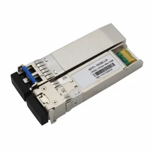
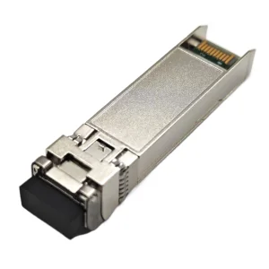
Metal enclosure for lower electromagnetic interference (EMI).
2-wire interface with integrated Digital Diagnostic Monitoring (DDM).
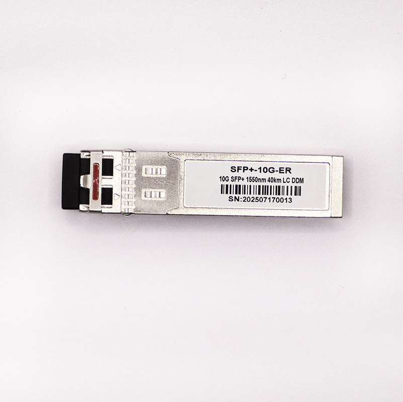
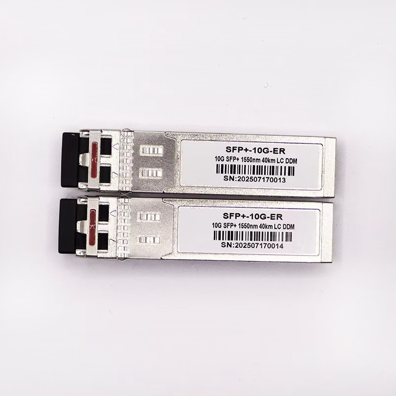
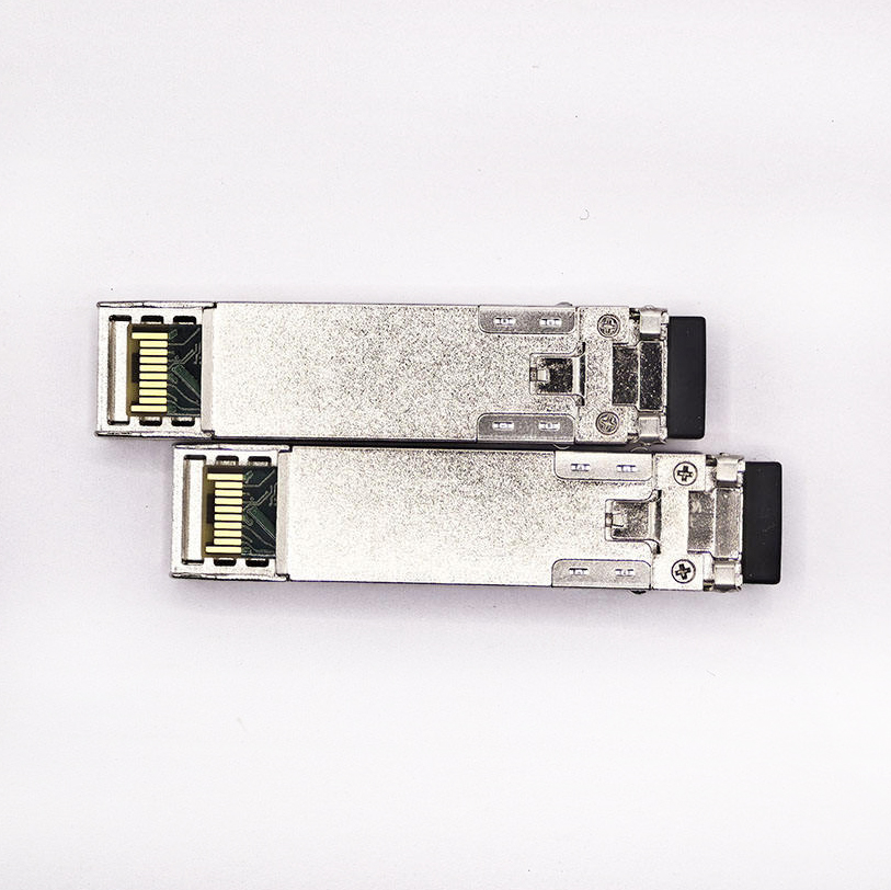
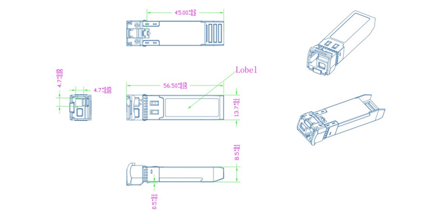
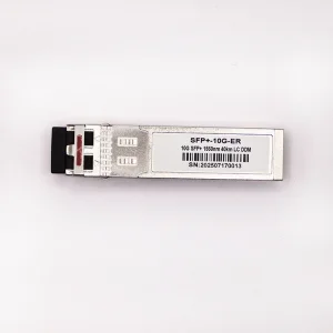
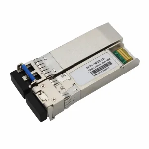
Hot-pluggable SFP+ footprint with duplex LC connector.
Single 3.3V power supply with dissipation < 1.5 W.
Case operating temperature range: 0°C to 70°C.
Pin Descriptions
Pin Symbol Name/Description NOTE
1 VEET Transmitter Ground (Common with Receiver Ground) 1
2 TFAULT Transmitter Fault. 2
3 TDIS Transmitter Disable. Laser output disabled on high or open. 3
4 SDA 2-wire Serial Interface Data Line 4
5 SCL 2-wire Serial Interface Clock Line 4
6 MOD_ABS Module Absent. Grounded within the module 4
7 RS0 Rate Select 0 5
8 LOS Loss of Signal indication. Logic 0 indicates normal operation. 6
9 RS1 No connection required 1
10 VEER Receiver Ground (Common with Transmitter Ground) 1
11 VEER Receiver Ground (Common with Transmitter Ground) 1
12 RD- Receiver Inverted DATA out. AC Coupled -
13 RD+ Receiver Non-inverted DATA out. AC Coupled -
14 VEER Receiver Ground (Common with Transmitter Ground) 1
15 VCCR Receiver Power Supply -
16 VCCT Transmitter Power Supply -
17 VEET Transmitter Ground (Common with Receiver Ground) 1
18 TD+ Transmitter Non-Inverted DATA in. AC Coupled. -
19 TD- Transmitter Inverted DATA in. AC Coupled. -
20 VEET Transmitter Ground (Common with Receiver Ground) 1
Pin Notes:
  1. Circuit ground is internally isolated from chassis ground.
  2. TFAULT is an open collector/drain output, which should be pulled up with a 4.7k – 10k Ohms resistor on the host board if intended for use. Pull up voltage should be between 2.0V to Vcc + 0.3V. A high output indicates a transmitter fault caused by either the TX bias current or the TX output power exceeding the preset alarm thresholds. A low output indicates normal operation. In the low state, the output is pulled to <0.8V.
  3. Laser output disabled on TDIS >2.0V or open, enabled on TDIS <0.8V.
  4. Should be pulled up with 4.7kΩ - 10kΩ host board to a voltage between 2.0V and 3.6V. MOD_ABS pulls line low to indicate module is plugged in.
  5. Internally pulled down per SFF-8431 Rev 4.1.
  6. LOS is open collector output. It should be pulled up with 4.7kΩ – 10kΩ on host board to a voltage between 2.0V and 3.6V. Logic 0 indicates normal operation; logic 1 indicates loss of signal.

Protocol & Diagnostics:

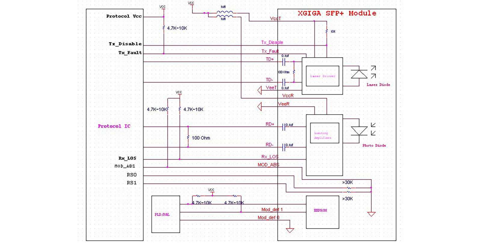
OP-SFP+-ER transceivers support the 2-wire serial communication protocol as defined in the SFP+ MSA. The standard SFP serial ID provides access to identification information that describes the transceiver’s capabilities, standard interfaces, and other key details.

Additionally, SFP+ transceivers provide a unique enhanced digital diagnostic monitoring interface (DDM), which allows real-time access to device operating parameters such as transceiver temperature, laser bias current, transmitted optical power, received optical power and transceiver supply voltage. It also defines a sophisticated system of alarm and warning flags, which alerts end-users when particular operating parameters are outside of a factory set normal range.

The SFP MSA defines a 256-byte memory map in EEPROM that is accessible over a 2-wire serial interface at the 8 bit address 1010000X (A0h). The digital diagnostic monitoring interface makes use of the 8 bit address 1010001X (A2h), so the originally defined serial ID memory map remains unchanged.

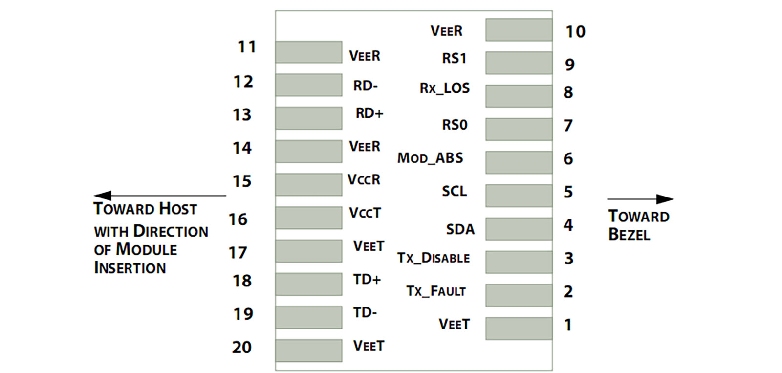
The operating and diagnostics information is monitored and reported by a Digital Diagnostics Transceiver Controller (DDTC) inside the transceiver, which is accessed through a 2-wire serial interface. When the serial protocol is activated, the serial clock signal (SCL, Mod Def 1) is generated by the host. The positive edge clocks data into the SFP transceiver into those segments of the E2PROM that are not write-protected. The negative edge clocks data from the SFP transceiver. The serial data signal (SDA, Mod Def 2) is bi-directional for serial data transfer. The host uses SDA in conjunction with SCL to mark the start and end of serial protocol activation. The memories are organized as a series of 8-bit data words that can be addressed individually or sequentially.

Electrical Characteristics
Parameter Symbol Min Typ Max Unit NOTE
Supply Voltage Vcc 3.14 3.3 3.46 V -
Supply Current Icc - - 450 mA -
Transmitter
Input differential impedance Rin - 100 - Ω 1
Single ended data input swing Vin,pp 180 - 700 mV -
Transmit Disable Voltage VD Vcc–1.3 - Vcc V -
Transmit Enable Voltage VEN Vee - Vee+ 0.8 V 2
Transmit Disable Assert Time - - - 10 us -
Receiver
Differential data output swing Vout,pp 300 - 850 mV 3
Data output rise time tr 28 - - ps 4
Data output fall time tf 28 - - ps 4
LOS Fault VLOS fault Vcc–1.3 - VccHOST V 5
LOS Normal VLOS norm Vee - Vee+0.8 V 5
Power Supply Rejection PSR 100 - - mVpp 6
Electrical Notes:
  1. Connected directly to TX data input pins. AC coupled thereafter.
  2. Or open circuit.
  3. Into 100 ohms differential termination.
  4. 20 – 80 %.
  5. Loss Of Signal is LVTTL. Logic 0 indicates normal operation; logic 1 indicates no signal detected.
  6. Receiver sensitivity is compliant with power supply sinusoidal modulation of 20 Hz to 1.5 MHz up to specified value applied through the recommended power supply filtering network.
Document Revision History
Version No. Date Description
1.0 2010-09-01 Preliminary datasheet
2.0 2011-09-10 Update format and logo
3.0 2012-08-03 Update power spec -1~4 to -1~3
Frequently Asked Questions
What is the maximum transmission distance of the SFP+ 10G ER transceiver?
The SFP+ 10G ER transceiver supports data transmission distances of up to 40 km over single-mode fiber (SMF) using a wavelength of 1550nm.
Does this optical module support diagnostic monitoring?
Yes, it features a 2-wire serial interface with integrated Digital Diagnostic Monitoring (DDM/DOM), allowing real-time monitoring of temperature, supply voltage, laser bias current, and transmit/receive optical power.
What type of connector does the SFP+ 10G ER module use?
The module is designed with a standard duplex LC connector and is compliant with SFP+ MSA specifications.
Is the transceiver hot-pluggable?
Yes, it features a hot-pluggable SFP+ footprint, which allows it to be inserted or removed from the host device port without powering down the network equipment.
What are the power requirements and operating temperatures for this module?
It operates on a single 3.3V power supply with a power dissipation of less than 1.5W. The standard case operating temperature range is 0°C to 70°C.
Is this module compliant with industry environmental and safety standards?
Yes, the transceiver is RoHS compliant and meets electromagnetic compatibility (EMC) regulations, Class 1 laser eye safety standards (FDA/IEC/EN), and ESD immunity standards.

Related Products