Direct manufacturer distribution channels for high-density, carrier-grade network architectures.
An architectural guide to 100G Extended Reach (ER) optical systems, link budgets, and dispersion management in metro core networks.
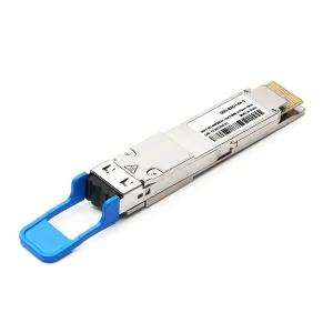
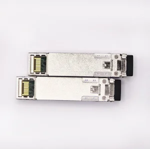
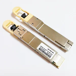
The standard 100G ER4 transceivers operate using the LAN-WDM wavelength grid (1295.56nm, 1300.05nm, 1304.86nm, and 1309.14nm). By mapping 4 separate 25Gbps channels into the zero-dispersion window of G.652 Single-Mode Fiber (SMF), the design minimizes chromatic dispersion penalties over long distances without needing complex dispersion compensation modules (DCM).
Standard 100G LR4 links are limited to 10km. 100G ER4 extends this limit up to 30km (without FEC) and 40km (with FEC). Achieving this requires high-performance Semiconductor Optical Amplifiers (SOA) or highly sensitive Avalanche Photodiode (APD) receivers at the destination to offset the cumulative attenuation of 0.35 dB/km typically encountered in single-mode fiber infrastructure.
OEM-grade 100G ER modules feature integrated DDM/DOM (Digital Diagnostic Monitoring) complying with SFF-8636 standards. This allows operators to monitor real-time metrics including TX/RX optical power, operating temperature, laser bias current, and module supply voltage to diagnose system degradation before terminal downtime occurs.
| Parameter / Specification | 100GBASE-LR4 QSFP28 | 100GBASE-ER4 Lite (with Host FEC) | 100GBASE-ER4 QSFP28 (Standard) |
|---|---|---|---|
| Operating Wavelengths | 1295.56, 1300.05, 1304.86, 1309.14 nm | 1295.56, 1300.05, 1304.86, 1309.14 nm | 1295.56, 1300.05, 1304.86, 1309.14 nm |
| Maximum Distance Target | 10 km | 30 km (Non-FEC) / 40 km (with FEC) | 40 km |
| Receiver Component | PIN Photodiode | APD / SOA + PIN Photodiode | APD / SOA + PIN Photodiode |
| Max Power Consumption | ≤ 3.5 W | ≤ 4.0 W | ≤ 4.5 W |
| Optical Power Budget | 8.5 dB | 15.0 dB | 18.0 dB (or 21.0 dB minimum) |
Why global telecom operators and hyperscale data centers leverage Chinese fabrication lines for high-speed active optical modules.
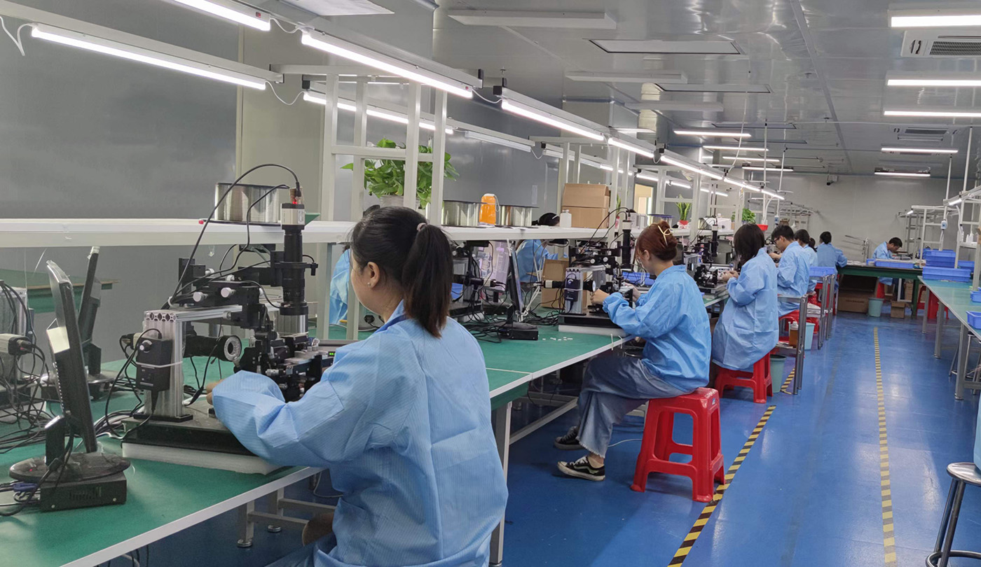
Modern Chinese manufacturing facilities utilize automated COB packaging. By placing optical chips directly onto the PCB substrate, manufacturers reduce parasitic capacitance, minimize thermal resistance, and improve optical alignment tolerances. This level of process control ensures high yields and consistent performance for 100G and 400G transceivers.
Every module undergoes rigorous testing. Real-time eye diagram monitoring, bit error rate (BER) checks at various temperatures (-40°C to +85°C for industrial variants), and compatibility sweeps across multiple switch operating systems (Cisco, Arista, Juniper, Dell) ensure that shipped hardware works reliably out of the box.
From the precise drawing of optical fiber to ceramic ferrule fabrication and cleanroom transceivers assembly, China's hardware ecosystem streamlines procurement. This localized ecosystem cuts component lead times, allowing fast turnaround on customized OEM orders and large-scale deployments.
100G ER transceivers are critical components in modern telecommunication and enterprise network topologies.
With 5G deployment calling for wider bandwidth and lower latency, 100G links are moving closer to the network edge. 100G ER4 links connect remote radio units (RRU) and baseband processing pools (BBU/DU) over distances that standard LR4 modules cannot bridge. This allows operators to centralize baseband processing and reduce regional hub facility requirements.
For cloud providers and large enterprises utilizing multiple campuses, DCI links require reliable, high-capacity, long-reach options. Deploying 100G ER4 QSFP28 transceivers over dark single-mode fiber links up to 40km allows these enterprises to maintain optical connectivity without needing mid-span active regeneration stations or amplifiers. This lowers both deployment costs (CapEx) and long-term operating costs (OpEx).

Kocent Optec Limited, established in 2012 in Hong Kong as a high-tech communication enterprise, is one of China's leading fiber optic termination product manufacturers and solution providers.
We are dedicated to developing and manufacturing fiber optic communication products ranging from passive to active categories for telecommunication networks, enterprise networks, and data centers.
By leveraging our extensive experience and production capacity gained over the years, we improve outcomes for our clients, helping them build competitive capabilities and scale. We prioritize customer collaboration and position ourselves as a partner in fiber optic connection solutions. We believe our technical standards are your long-term advantage.
With more than 13 years of experience in manufacturing telecommunication fiber optic products, we strictly follow fiber optic industry standards. We use mature scientific methods to deliver your products on time and ensure that 100% of products are tested and inspected before shipment.
Years of sales and service experience have enabled us to win customers from different regions. Today, we have customers from East Asia, Southeast Asia, Middle East, Eastern Europe, Western Europe, Northern Europe, South America, North America, North Africa, and South Africa.
Win-win cooperation is our constant goal. Many of our OEM and ODM products have won telecom operator tenders and satisfy end-user requests worldwide.
Our passive and active components are qualified and integrated into the supply networks of key telecom companies worldwide.
Frequently asked technical and operational questions regarding 100G ER transceivers and global deployment protocols.
What is the core difference between 100G ER4 and 100G ER4 Lite?
100G ER4 standard modules can reach up to 40km over Single-Mode Fiber (SMF) using an internal optical amplifier (SOA) and APD receiver without requiring Forward Error Correction (FEC) on the host switch. 100G ER4 Lite, on the other hand, requires FEC (KR4 FEC) enabled on the host port to achieve the same 40km range. Without host FEC, ER4 Lite is generally rated for up to 30km transmission.
Why does 100G ER4 use LAN-WDM instead of CWDM wavelengths?
LAN-WDM uses a tighter channel spacing (around 800GHz) centered near the zero-dispersion wavelength of Single-Mode Fiber (1310nm). This narrow spacing minimizes chromatic dispersion over 40km. CWDM channels are spaced wider (20nm apart), stretching from 1270nm to 1610nm. While CWDM is more cost-effective for shorter distances, its outer channels suffer from high dispersion and attenuation over extended runs, making it unsuitable for 40km transmission.
What compatibility parameters must an OEM manufacturer verify for 100G transceivers?
An OEM manufacturer must write the correct EEPROM values (complying with SFF-8636) to ensure the host switch does not reject the transceiver. This includes coding the correct Vendor Name, OUI, Part Number, and checksums. Modules must also undergo physical validation on host platforms (such as Cisco IOS, Arista EOS, and Juniper Junos) to verify proper link-up, DDM reading, and port initialization.
How does ambient temperature affect 100G ER modules?
100G ER modules generate significant heat due to the high-performance EML lasers and internal SOAs/APDs. Standard commercial-grade modules operate from 0°C to 70°C. For industrial deployments (such as outdoor cabinets and telecom towers), manufacturers use industrial-grade components and customized thermal pads, rating the transceivers to operate from -40°C to +85°C without performance degradation.
What are the power budget requirements for a reliable 40km link?
A reliable 40km link over G.652 SMF typically requires an optical power budget of at least 18dB. This accounts for fiber attenuation (approx. 0.35dB/km, totaling 14dB), splice losses, connection points, and a system safety margin of 2-3dB to guard against future fiber degradation or macro-bends.
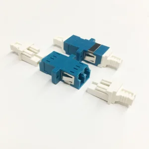
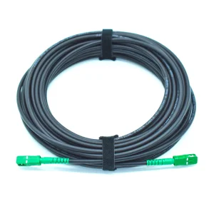
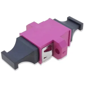
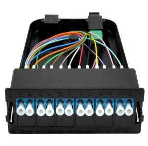
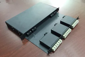
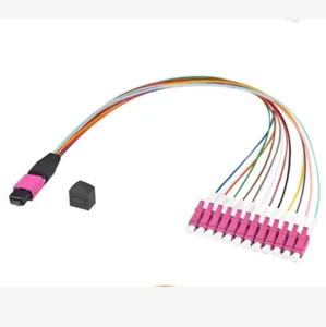
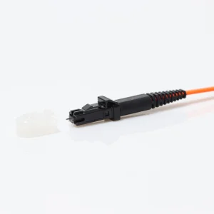
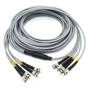
High-density fiber distribution, jumpers, and connectivity adapters designed for carrier networks.