Key Features & Characteristics
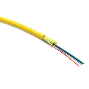
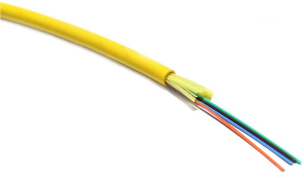
- The Distribution Fanout Tight Buffer Indoor Fiber Optical Cable uses 2~48 core (or more) 900μm or 600μm tight buffer fiber as optical sub cable. Normally it is covered with PVC or LSZH, and optionally PE or Nylon.
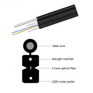
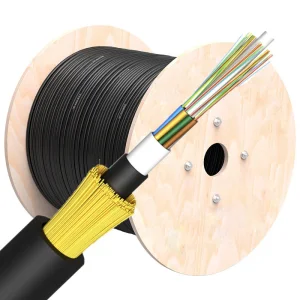
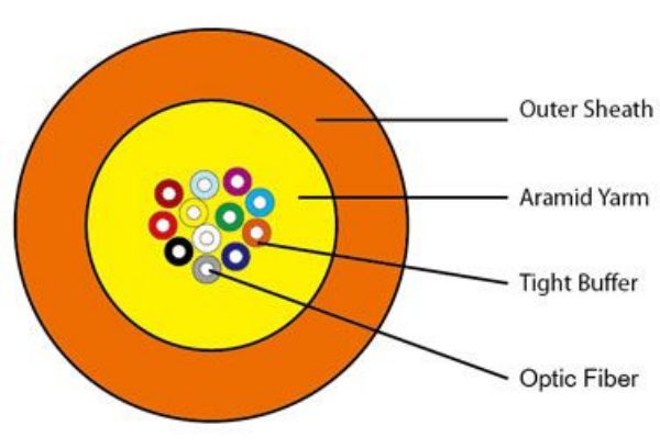
- The tight buffer fiber is wrapped with a layer of aramid yarn as a strength member, then completed with a layer of PVC or LSZH material as an outer jacket.
- Good mechanical and environmental characteristics ensure reliable long-term performance.
- Flame retardant characteristics meet the requirements of relevant industry standards.
- The mechanical characteristics of the jacket meet the requirements of relevant standards.
- Soft, flexible, easy to lay and splice, featuring large capacity data transmission.
- Designed to meet various rigorous requirements of the market and clients.
Jacket Color Code Guide:
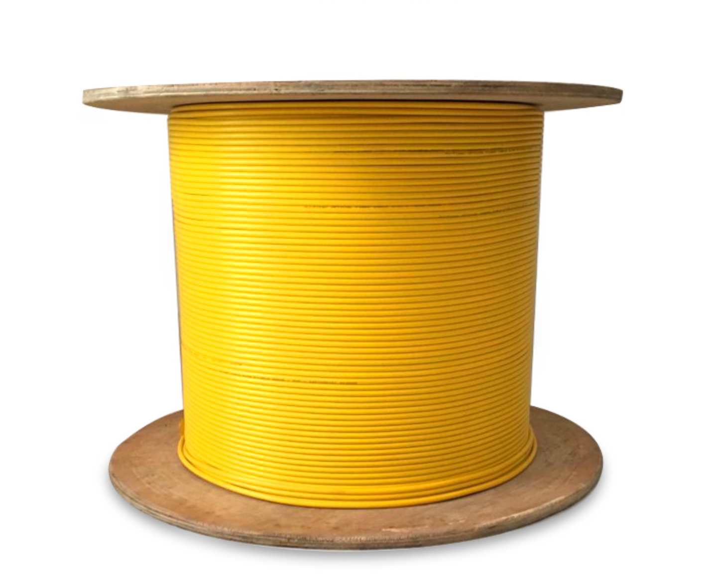
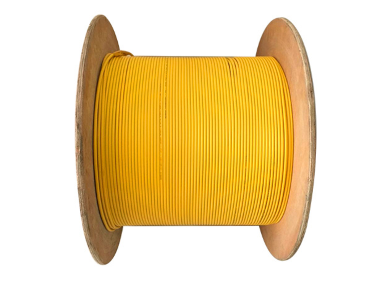
• Single mode: Yellow
• Multimode OM1 / OM2: Orange
• Multimode OM3 / OM4: Aqua
• Multimode OM4: Violet
• Multimode OM5: Lime
*Other custom colors are optional.
Mechanical & Physical Properties
| Fanout Indoor Fiber Optical Cable (GJFJV) |
Cable Diameter |
Weight |
| 2 cores |
4.5mm |
22.00kg/km |
| 4 cores |
4.5mm |
22.00kg/km |
| 6 cores |
4.5mm |
23.00kg/km |
| 8 cores |
5.5mm |
27.00kg/km |
| 10 cores |
5.5mm |
30.00kg/km |
| 12 cores |
6.0mm |
35.00kg/km |
| Storage temperature (℃) |
-20 to +60 |
| Min Bending Radius (mm) |
Long term |
10D |
| Min Bending Radius (mm) |
Short term |
20D |
| Min allowable Tensile Strength (N) |
Long term |
200 |
| Min allowable Tensile Strength (N) |
Short term |
600 |
| Crush Load (N/100mm) |
Long term |
200 |
| Crush Load (N/100mm) |
Short term |
1000 |
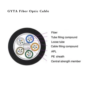
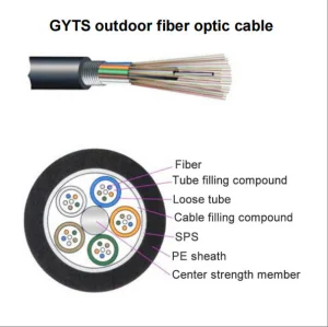
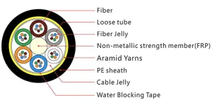
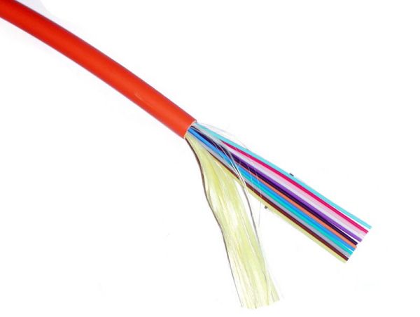
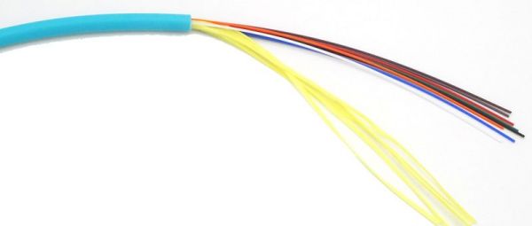
Cable Structure Images
Single mode 4 cores Cable
Multimode OM3 8 cores Cable
Multimode 50/125 24 cores Cable
Cable Cross Section View
Technical Specifications
| Fiber style |
Unit |
SM G652 |
SM G652D |
SM G657A |
MM 50/125 |
MM 62.5/125 |
MM OM3-300 |
| condition |
nm |
1310/1550 |
1310/1550 |
1310/625 |
850/1300 |
850/1300 |
850/1300 |
| attenuation |
dB/km |
≤0.36/0.23 |
≤0.34/0.22 |
≤0.35/0.21 |
≤3.0/1.0 |
≤3.0/1.0 |
≤3.0/1.0 |
| Dispersion |
1550nm |
Ps/(nm*km) |
---- |
≤18 |
≤18 |
---- |
---- |
---- |
| |
1625nm |
Ps/(nm*km) |
---- |
≤22 |
≤22 |
---- |
---- |
---- |
| Bandwidth |
850nm |
MHZ.KM |
---- |
---- |
|
≥400 |
≥160 |
|
| |
1300nm |
MHZ.KM |
---- |
---- |
|
≥800 |
≥500 |
|
| Zero dispersion wavelength |
nm |
≥1302 ≤1322 |
≥1302 ≤1322 |
≥1302 ≤1322 |
---- |
---- |
≥1295, ≤1320 |
| Zero dispersion slope |
nm |
≤0.092 |
≤0.091 |
≤0.090 |
---- |
---- |
---- |
| PMD Maximum Individual Fiber |
|
≤0.2 |
≤0.2 |
≤0.2 |
---- |
---- |
≤0.11 |
| PMD Design Link Value |
Ps(nm2*km) |
≤0.12 |
≤0.08 |
≤0.1 |
---- |
---- |
---- |
| Fibre cutoff wavelength λc |
nm |
≥1180 ≤1330 |
≥1180 ≤1330 |
≥1180 ≤1330 |
---- |
---- |
---- |
| Cable cutoff wavelength λcc |
nm |
≤1260 |
≤1260 |
≤1260 |
---- |
---- |
---- |
| MFD |
1310nm |
um |
9.2±0.4 |
9.2±0.4 |
9.0±0.4 |
---- |
---- |
---- |
| |
1550nm |
um |
10.4±0.8 |
10.4±0.8 |
10.1±0.5 |
---- |
---- |
---- |
| Numerical Aperture(NA) |
|
---- |
---- |
---- |
0.200± 0.015 |
0.275±0.015 |
0.200±0.015 |
| Step (mean of bidirectional measurement) |
dB |
≤0.05 |
≤0.05 |
≤0.05 |
≤0.10 |
≤0.10 |
≤0.10 |
| Irregularities over fiber length and point |
dB |
≤0.05 |
≤0.05 |
≤0.05 |
≤0.10 |
≤0.10 |
≤0.10 |
| Discontinuity |
|
| Difference backscatter coefficient |
dB/km |
≤0.05 |
≤0.03 |
≤0.03 |
≤0.08 |
≤0.10 |
≤0.08 |
| Attenuation uniformity |
dB/km |
≤0.01 |
≤0.01 |
≤0.01 |
|
|
|
| Core diameter |
um |
9 |
9 |
9 |
50±1.0 |
62.5±2.5 |
50±1.0 |
| Cladding diameter |
um |
125.0±0.1 |
125.0±0.1 |
125.0±0.1 |
125.0±0.1 |
125.0±0.1 |
125.0±0.1 |
| Cladding non-circularity |
% |
≤1.0 |
≤1.0 |
≤1.0 |
≤1.0 |
≤1.0 |
≤1.0 |
| Coating diameter |
um |
242±7 |
242±7 |
242±7 |
242±7 |
242±7 |
242±7 |
| Coating/chaffinch concentrically error |
um |
≤12.0 |
≤12.0 |
≤12.0 |
≤12.0 |
≤12.0 |
≤12.0 |
| Coating non circularity |
% |
≤6.0 |
≤6.0 |
≤6.0 |
≤6.0 |
≤6.0 |
≤6.0 |
| Core/cladding concentricity error |
um |
≤0.6 |
≤0.6 |
≤0.6 |
≤1.5 |
≤1.5 |
≤1.5 |
| Curl (radius) |
um |
≤4 |
≤4 |
≤4 |
---- |
---- |
---- |
Applications & Deployments
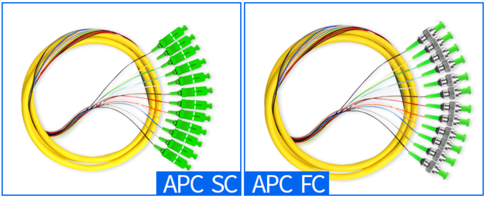
- Used in pigtails and patch cords.
- Used as interconnect lines of equipment.
- Used in optical connections in optical communication rooms, data centers, and optical distribution frames.
- Used in indoor cabling, especially as a distribution cable.
Frequently Asked Questions (FAQ)
1. What is the core capacity range for this Distribution Fanout Tight Buffer Cable?
The cable typically supports core capacities ranging from 2 to 48 cores (or more) utilizing 900μm or 600μm tight buffer fibers as the optical sub-unit.
2. What color coding standard is used for the cable jackets?
The jacket color denotes the fiber type: Yellow for Single Mode, Orange for Multimode OM1/OM2, Aqua for Multimode OM3/OM4, Violet for Multimode OM4, and Lime for Multimode OM5. Other jacket colors are optional.
3. What materials are used for the strength member and outer jacket?
The tight buffer fibers are wrapped with a layer of aramid yarn which serves as the primary strength member, and is finished with an outer jacket made of high-quality PVC or LSZH (Low Smoke Zero Halogen) material. PE and Nylon are also optional.
4. What are the minimum bending radius and tensile strength limits?
The cable features a minimum bending radius of 10D (Long term) and 20D (Short term). The minimum allowable tensile strength is 200N for long-term applications and 600N for short-term mechanical stress.
5. Where is this indoor fiber optical cable typically applied?
It is primarily designed for optical patch cords and pigtails, device interconnection lines, and optical setups within telecommunication server rooms, datacenters, distribution frames, and general indoor riser/plenum cabling.
6. Does the cable meet fire safety compliance requirements?
Yes, the flame retardant properties of this indoor fiber optical cable comply with relevant industry test standards for safe indoor infrastructure installations.