1 / 4
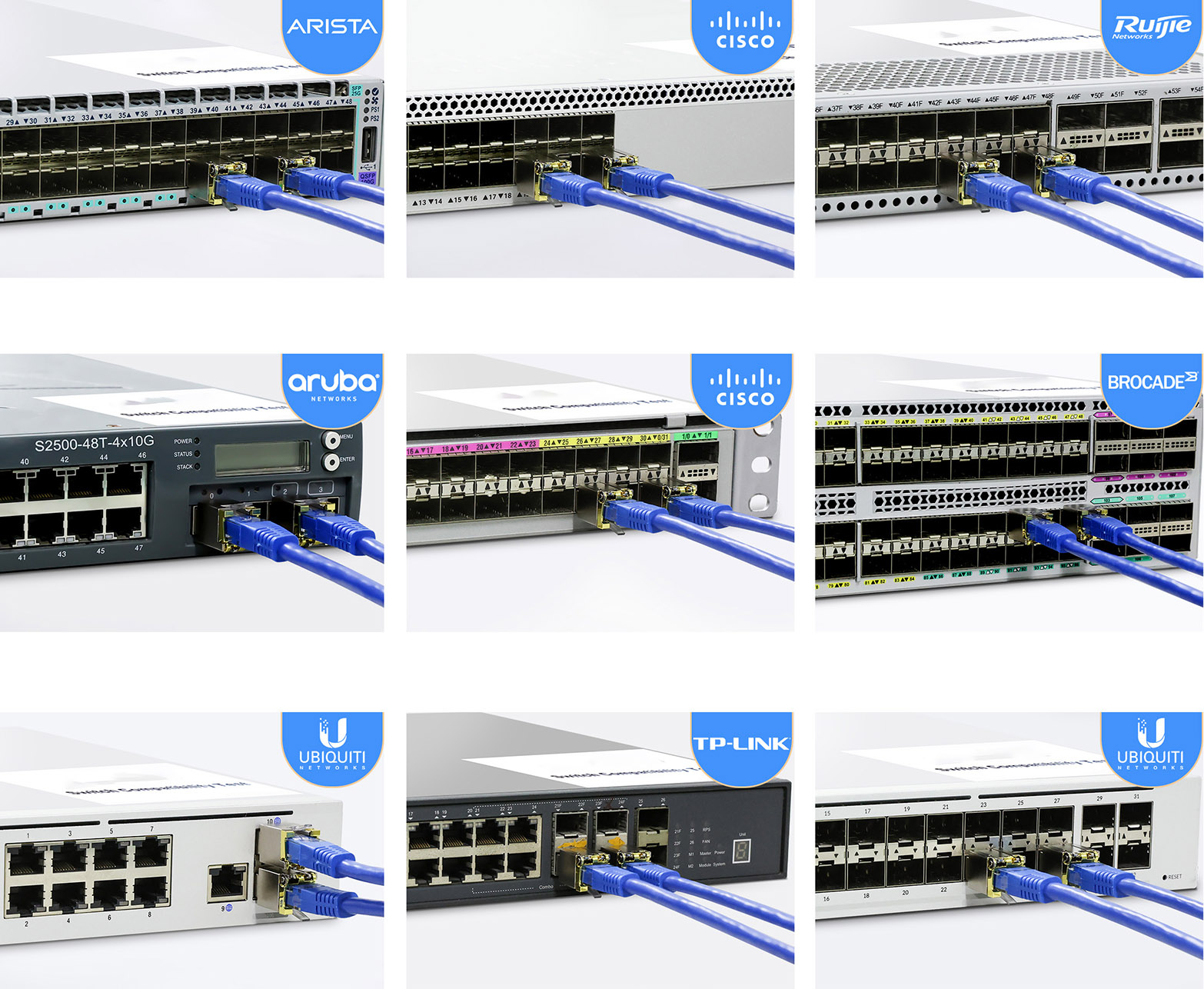
Small Form-factor Pluggable (SFP) is a compact, hot-pluggable network interface module format used for both telecommunication and data communications applications. An SFP interface on networking hardware is a modular slot for a media-specific transceiver, such as for a fiber-optic cable or a copper cable.
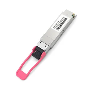
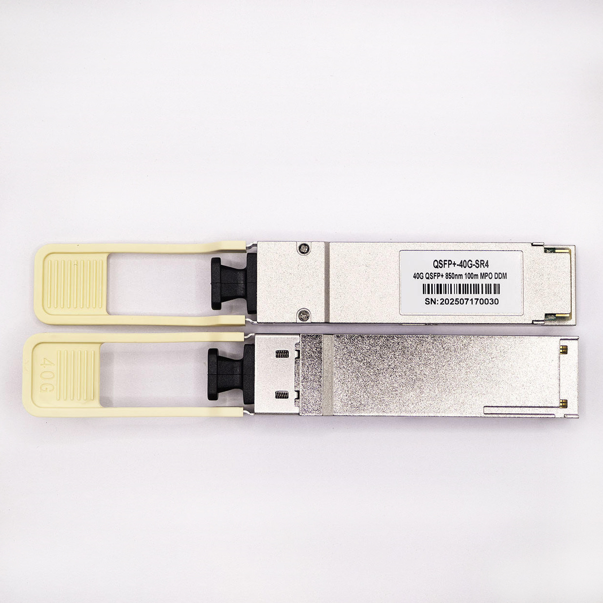
QSFP (Quad Small Form-factor Pluggable) is a type of transceiver module used for high-speed data transmission in networking devices, particularly in data centers and high-performance computing environments. It's designed to support multiple channels (typically four) and can handle data rates ranging from 10 Gbps to 400 Gbps, depending on the specific module type.
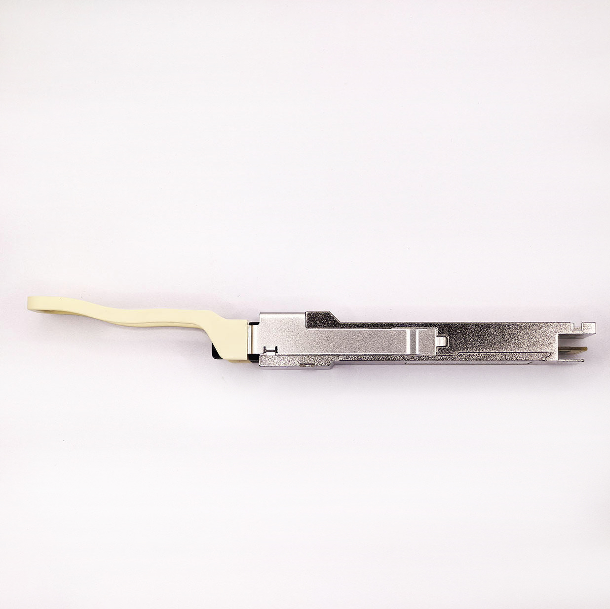
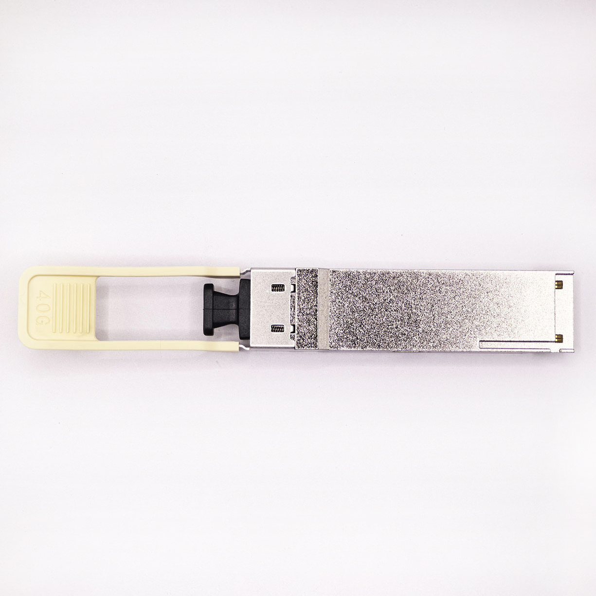
QSFP modules are designed to be compact, allowing for a high number of connections in a relatively small space.
They can be inserted and removed from a device while it's powered on, without causing disruptions to the network.
QSFP modules typically have four channels, each capable of transmitting data, allowing for higher bandwidth and data rates.
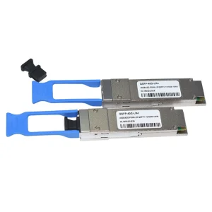
Different QSFP variants exist, such as QSFP+, QSFP28, QSFP56, and QSFP-DD, supporting different speeds from 40Gbps to 400Gbps and beyond.
QSFP modules are used in a wide range of applications, including data center interconnects, high-performance computing, and telecommunications networks.
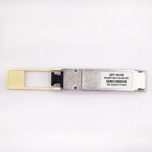
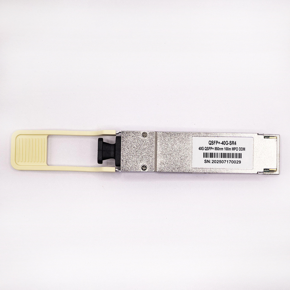
The OP-QSFP+-01 is designed for use in 40 Gigabit per second links over multimode fiber. They are compliant with the QSFP+ MSA and IEEE 802.3ba 40GBASE-SR4.
The optical transmitter portion of the transceiver incorporates a 4-channel VCSEL (Vertical Cavity Surface Emitting Laser) array, a 4-channel input buffer and laser driver, diagnostic monitors, control and bias blocks. For module control, the control interface incorporates a Two Wire Serial interface of clock and data signals. Diagnostic monitors for VCSEL bias, module temperature, transmitted optical power, received optical power and supply voltage are implemented and results are available through the TWS interface. Alarm and warning thresholds are established for the monitored attributes. Flags are set and interrupts generated when the attributes are outside the thresholds. Flags are also set and interrupts generated for loss of input signal (LOS) and transmitter fault conditions. All flags are latched and will remain set even if the condition initiating the latch clears and operation resumes. All interrupts can be masked and flags are reset by reading the appropriate flag register. The optical output will squelch for loss of input signal unless squelch is disabled. Fault detection or channel deactivation through the TWS interface will disable the channel. Status, alarm/warning and fault information are available via the TWS interface.
The optical receiver portion of the transceiver incorporates a 4-channel PIN photodiode array, a 4-channel TIA array, a 4 channel output buffer, diagnostic monitors, and control and bias blocks. Diagnostic monitors for optical input power are implemented and results are available through the TWS interface. Alarm and warning thresholds are established for the monitored attributes. Flags are set and interrupts generated when the attributes are outside the thresholds. Flags are also set and interrupts generated for loss of optical input signal (LOS). All flags are latched and will remain set even if the condition initiating the flag clears and operation resumes. All interrupts can be masked and flags are reset upon reading the appropriate flag register. The electrical output will squelch for loss of input signal (unless squelch is disabled) and channel de-activation through TWS interface. Status and alarm/warning information are available via the TWS interface.